Home » Products » Equipment for Oil and Gas Industries » Gas Pumping and Turbo-Compressor Units
One of the main production activity of JSC “SMNPO – Engineering” is manufacture and supply of gas-pumping, turbocompressor, electric-driven gas-pumping and electric-driven compressor units, both separately and as part of modular compressor stations.
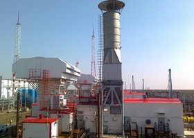
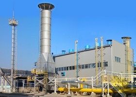
Depending on the customer’s requirements, the gas pumping equipment is designed and supplied for various parameters in terms of productivity and power, discharge pressure and compression ratio.
Possessing a powerful production and scientific and technical potential, the enterprise can, in the shortest possible time, complete the development of design and technological documentation, manufacture, test and supply the customer with the required equipment, carry out its installation, commissioning and, if necessary, provide its service.
The company specializes mainly in the creation of gas pumping equipment of medium and high power from 6.3 to 25 MW with gas turbine and electric drives.
All units are equipped with microprocessor control systems based on modern element base.
At the request of the Customers, the units can be completed with exhaust gases heat recovery units.
JSC “SMNPO – Engineering” has mastered the production of units with non-lubricated “dry” compressors with gas dynamic seals, electromagnetic bearings and a “dry” transferring coupling.
The Company has also mastered the production of gas-pumping units with centrifugal compressors in corrosion-resistant design for compressing hydrogen sulfide-containing gas.
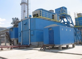
At the request of the Customer, we can supply units with the required performance characteristics, both with “dry” compressors and with oil compressors, with a gas turbine engine of any global manufacturer or with an electric drive, in modular container design or in individual sheltered buildings.
To compress associated petroleum gas, complete compressor lines have been created, including turbocompressor units (TKA) with high compression ratios (2-20 or more), intermediate and end gas coolers and separators. The whole range of gas turbine engines is used as a drive, both for GPA and TKA. TKA can be supplied with or without gas coolers and separators.
JSC SMNPO – Engineering has created a large range of GPAs with the capacity:
| 6.3 МW: | 8 МW: | 10 МW: |
| GPА-C-6.3, GPА-C-6.3V with airderivative engine NК-12SТ; GPА-C-6.3А with airderivative engine D-336; GPА-C-6.3S with marine gas-turbine drive DТ-71P3. | GPА-C-8 with engine GTD-6.3RМ/8; | GPА-C-10Б with engine NК-14SТ-10. |
| 12 МВт: | 16 МВт: | 25 МВт: |
GPА-C-12П with airderivative engine PS-90GP-1. | GPА-C-16 with airderivative engine NК-16SТ; | GPА-C-25 with airderivative engine NК-36СТ; |
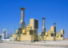 Depending on the customer’s requirements, the gas pumping equipment is designed and supplied for various parameters in terms of productivity and power, discharge pressure and compression ratio.
GPU identification legend, example: GPA-C1-16АD/76-1.44М1
GPA – gas pumping unit;
C – the unit includes centrifugal compressor C1…C5 – compressor rotor bundles modifications;
16 – engine capacity, MW;
А – gas-turbine engine type: А – airderivative, modification D336-2; B – airderivative NК-14SТ and NК-36SТ; V – airderivative NК-12SТ;
S – marine, modification DG-90; L – airderivative, modification АL-31; P – airderivative, modification PS-90; without letter – airderivative GTD-6.3RM/8;
D – in an individual modular self-supporting shelter building, without letter D – container modular unit design.
76 – compressor discharge pressure, kgf/сm2; 1.44 – pressure ratio
М1 – compressor design: М – with magnetic rotor suspension and dry gas seal («dopeless» compressor) М1 – with oil bearings and a dry gas seal.
Also, compressors can be manufactured in corrosion-resistant design of steel which is resistant to sulfurous gas (Н2S). This design is indicated by letter «К», after discharge pressure value.
To order the equipment you are interested in, please complete the Questionnaire.
№ | Suction Pressure, kgf/сm2 | Discharge Pressure, kgf/сm2 | Flow Rate Capacity, MMCMD | Recommended GPU |
1 | 6.0 | 14.0 | 3.3 | GPA-C6.3А/14-2.3 |
2 | 7.0 | 21.0 | 8.3 | GPA-C5-16S/21-3,0М1 |
3 | 10.0 | 20.0 | 6.0 | GPA-C-8D/20-2.0М1 |
4 | 10.0 | 21.0 | 12.5 | GPA-C5-16S/21-2.2 |
5 | 18.0 | 41.0 | 5.0 | GPA-C-8B/41-2.2 |
6 | 33.0 | 76.0 | 12.0 | GPA-C5-16SD/76-2.2М1 |
7 | 33.0 | 55.0 | 8.0 | GPA-C-8А/55-1.7 |
8 | 34.0 | 76.0 | 12.0 | GPA-C5-16S/76-2.2 |
9 | 35.0 | 73.0 | 12.7 | GPA-C-16/73-2.1М1 |
10 | 36.0 | 76.0 | 3.0 | GPA-C-6.3/76-2.1М1 |
11 | 38.0 | 56.0 | 17.3 | GPA-C-10B/56-1.44 |
12 | 38.0 | 56.0 | 17.0 | GPA-C-10BD/56-1.44 |
13 | 45.0 | 76.0 | 4.5 | GPA-C-4.0А/76-1.7 |
14 | 45.0 | 76.0 | 21.5 | GPA-C3-16S/76-1.7М |
15 | 45.0 | 76.0 | 21.5 | GPA-C3-16S/76-1.7М |
16 | 45.0 | 100.0 | 12.5 | GPA-C-16/102-2.32М |
17 | 47.0 | 80.0 | 17.14 | GPA-C-16PD/80-1.7М1 |
18 | 50.0 | 74.0 | 20.0 | GPA-C1-25S/74-1.5М1 |
19 | 52.0 | 76.0 | 32.2 | GPA-C1-16L/76-1.44 |
20 | 52.0 | 76.0 | 47.24 | GPA-C1-25BD/76-1.44М |
21 | 52.0 | 76.0 | 47.0 | GPA-C1-25SD/76-1.44М |
22 | 55.0 | 76.0 | 12.0 | GPA-C-8/76-1.37 |
23 | 63.0 | 85.0 | 38.0 | GPA-C1-16S/85-1.35М1 |
24 | 68.0 | 92.0 | 27.1 | GPA-C1-25S/92-1.35М1 |
25 | 70.0 | 100.0 | 45.0 | GPA-C-25SD/100-1.44М |
26 | 72.0 | 100.0 | 48.0 | GPA-C-25SD/100-1.44М1 |
27 | 74.0 | 100.0 | 60.0 | GPA-C-25BD/100-1.35М |
28 | 74.0 | 100.0 | 60.0 | GPA-C-25SD/100-1.35М |
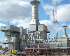 Depending on the customer’s requirements, the gas pumping equipment is designed and supplied for various parameters in terms of productivity and power, discharge pressure and compression ratio.
Turbocompressor identification legend, example: ТКА-C 25SD/0.58-5.5М1
ТКА – turbo-compressor package;
C – the unit includes centrifugal compressor;
25 – engine capacity, MW;
S – gas-turbine engine type: А – airderivative, modification D336-2; B – airderivative NК-14SТ and NК-36SТ; V – airderivative NК-12SТ;
S – marine, modification DG-90; L – airderivative, modification АL-31; P – airderivative, modification PS-90;
D – container modular unit design; 0.58 – suction pressure, МPа; 5.5 – discharge pressure, МPа;
М1 – compressor design: М – with magnetic rotor suspension and dry gas seal («dopeless» compressor)
М1 – with oil bearings and a dry gas seal.
To order the equipment you are interested in, please complete the Questionnaire.
№ | Suction Pressure МPа | Discharge Pressure МПа | Flow Rate Capacity, MMCMD | Recommended ТКА |
1 | 0.233 | 0.965 | 2.48 | ТHА-C-8B/0.233-0.965 |
2 | 0.2 | 4.7 | 16.55 | ТКА-C-12P/0.2-4.7М1 |
3 | 0.3 | 5.6 | 2.28 | ТКА-C-16/0.3-5.6М1 |
4 | 0.3 | 8.0 | 1.14 | ТКА-C-8BD/0.3-8.0 |
5 | 0.4 | 6.1 | 1.8 | ТКА-C-12/0.4-6.1М1 |
6 | 0.6 | 5.5 | 5.4 | ТКА-C-25SD/0.6-5.5М1 |
7 | 1.0 | 4.6 | 1.58 | ТКА-C-8S/1.0-4.6 |
8 | 1.75 | 7.6 | 1.65 | ТКА-C-6.3А/1.75-7.6 |
9 | 2.1 | 7.9 | 3.48 | ТКА-C-16/2.1-7.9М1 |
10 | 4.0 | 7.6 | 2.0 | ТКА-C-16/4.0-7.6 |
11 | 4.2 | 29.7 | 3.64 | ТКА-C-25S/4.2-29.7М1 |
12 | 6.5 | 15.3 | 6.23 | ТКА-C-16S/6.5-15.3М1 |
 Depending on the customer’s requirements, the gas pumping equipment is designed and supplied for various parameters in terms of productivity and power, discharge pressure and compression ratio.
Electrically Driven Compressor Units identification legend,
example, EКА-C-8/12-49М1 , EGPА-C-1,0/11-1,92М1
EGPА – electrically driven gas pumping unit. EКА – electrically driven compressor unit.
C – the unit includes centrifugal compressor, C1…C5 – compressor rotor bundles modifications;
8 (1.0) – engine capacity, MW; 12 (11) – suction pressure, kgf/сm2; 49 – discharge pressure, kgf/сm2; 1,92– pressure ratio;
М1 – compressor design: М – with magnetic rotor suspension and dry gas seal («dopeless» compressor) .
М1 – with oil bearings and a dry gas seal.
To order the equipment you are interested in, please complete the Questionnaire
№ | Suction Pressure kgf/сm2 | Discharge Pressure kgf/сm2 | Flow Rate Capacity, MMCMD | Recommended EКА , EGPA |
1 | 12,0 | 49,0 | 2,16 | EКА-C-8/12-49М1 |
2 | 35,0 | 74,0 | 2,119 | EКА-Ц-3,35/35-74М1 |
3 | 20 | 40,8 | 4,564 | EКА-Ц-8/20-40М1 |
4 | 40,06 | 76,15 | 5,507 | EКА-Ц-8/40-76М1 |
5 | 32,04 | 73,29 | 3,3091 | EКА-Ц-6,0/32-73М1 |
6 | 64.09 | 70.44 | 0.55 | EКА-Ц-0.18/65-71М1 |
7 | 1.09 | 24.98 | 2.61 | EКА-Ц-9.0/1.1-25M1 |
8 | 5.84 | 11.0 | 0.535 | EGPА-Ц-1.0/11-1.92М1 |
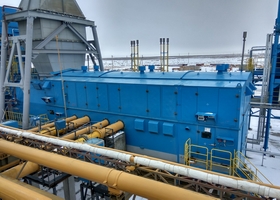
To complete compressor units with various drives (steam turbine, electric motor, gas turbine drive) provided by the customer or supplier of the unit, it is proposed to supply compressor modules as a part of the centrifugal compressor and ready-to-operate unit systems for connection to the drive.
Manufactured and Supplied Compressor Modules (CM):
Suction Pressure kgf/сm2 | Discharge Pressure kgf/сm2 | Flow Rate Capacity, MMCMD | Recommended CM |
5.25 ÷ 0.65 | 7.65 | 16.56 ÷ 2.18 | CM with compressors |
3.73 ÷ 0,89 | 7.65 | 5.8 ÷ 2.73 | CM with compressors 203 GC2 |
Details are specified in the Technical Catalog “COMPRESSOR EQUIPMENT and GAS-PUMPING UNITS“